|
CAPACITY |
|
L |
W |
W1 |
H |
T |
|
25/ 50/ 75kg |
mm |
50.8 |
19.1 |
12.7 |
63.5 |
M6 x 1.0
1/4-28UNF |
|
(inch) |
2.00 |
0.75 |
0.50 |
2.50 |
|
100kg |
mm |
50.8 |
25.4 |
19.1 |
76.2 |
M10 x 1.5 |
|
(inch) |
2.00 |
1.00 |
0.75 |
3.00 |
|
250/ 300lb |
mm |
50.8 |
19.1 |
12.7 |
76.2 |
3/8-24UNF |
|
(inch) |
2.00 |
0.75 |
0.50 |
3.00 |
|
250/ 500/ 750kg
500/ 750/ 1K/ 1.5Klb |
mm |
50.8 |
25.4 |
19.1 |
76.2 |
M12 x 1.75
1/2-20UNF |
|
(inch) |
2.00 |
1.00 |
0.75 |
3.00 |
|
1000/ 1500kg
2K/ 2.5K/ 3Klb |
mm |
50.8 |
31.8 |
25.4 |
76.2 |
M12 x 1.75
1/2-20UNF |
|
(inch) |
2.00 |
1.25 |
1.00 |
3.00 |
|
5K/ 7.5Klb |
mm |
76.2 |
31.8 |
25.4 |
107.9 |
3/4-16UNF |
|
(inch) |
3.00 |
1.25 |
1.00 |
4.25 |
|
2000/ 2500/ 5000kg |
mm |
76.2 |
38.1 |
31.8 |
100.4 |
M20 x 1.5 |
|
(inch) |
3.00 |
1.50 |
1.25 |
3.95 |
|
10Klb |
mm |
88.9 |
31.8 |
25.4 |
120.7 |
3/4-16UNF |
|
(inch) |
3.50 |
1.25 |
1.00 |
4.75 |
|
15Klb |
mm |
100.3 |
38.1 |
31.8 |
139.7 |
1-14UNS |
|
(inch) |
3.95 |
1.50 |
1.25 |
5.50 |
|
20Klb |
mm |
125.5 |
55.7 |
49.3 |
177.8 |
11/4-12UNF |
|
(inch) |
4.94 |
2.19 |
1.94 |
7.00 |
|
40Klb |
mm |
152.4 |
69.9 |
63.5 |
254.0 |
11/2-12UNF |
|
(inch) |
6.00 |
2.75 |
2.50 |
10.00 |
Document Number: 11710 www.vishaymg.com
Revision: 24-Jan-07 131
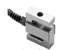
Model STC
Vishay Celtron S-Type Load Cell
|
SPECIFICATIONS |
|
PARAMETER |
VALUE |
UNIT |
|
NTEP/OIML Accuracy class |
NTEP III & IIIL |
Non-Approved |
|
|
Maximum no. of intervals (n) |
III 5000 single* IIIL 10000 single* |
2000 |
|
|
Y = Emax/Vmin |
10000 |
5000 |
Maximum available |
|
Standard capacities (Emax) |
25, 50, 75, 100, 250, 500, 750, 1000, 1500, 2000, 2500, 5000 |
kg |
|
Standard capacities (Emax) |
250, 300, 500, 750, 1K, 1.5K, 2K, 2.5K, 3K, 5K, 7.5K,
10K, 15K, 20K, 40K |
lbs |
|
Rated output-R.O. |
3.0 |
mV/V |
|
Rated output tolerance |
0.25 |
±% of rated output |
|
Zero balance |
1 |
±% of rated output |
|
Non linearity |
0.020 |
0.020 (SS: 0.05) |
±% of rated output |
|
Hysteresis |
0.020 |
0.020 (SS: 0.05) |
±% of rated output |
|
Non-repeatability |
0.020 |
±% of rated output |
|
Creep error (20 minutes) |
0.030 |
±% of rated output |
|
Zero return (20 minutes) |
0.030 |
±% of rated output |
|
Temperature effect on min. dead load output |
0.0015 |
0.0026 |
±% of rated output/°C |
|
Temperature effect on sensitivity |
0.0010 |
0.0015 |
±% of applied load/°C |
|
Compensated temperature range |
-10 to +40 |
°C |
|
Operating temperature range |
-20 to +60 |
°C |
|
Safe overload |
150 |
% of R.C. |
|
Ultimate overload |
300 |
% of R.C. |
|
Excitation, recommended |
10 |
Vdc or Vac rms |
|
Excitation, maximum |
15 |
Vdc or Vac rms |
|
Input impedance |
385±5 |
Ohms |
|
Output impedance |
350±3 |
Ohms |
|
Insulation resistance |
>5000 |
Mega-Ohms |
|
Construction |
Nickel plated alloy steel** |
|
|
Environmental protection |
IP67 |
|
* Capacities 250-20Klbs
** Stainless steel available
All specifications listed subject to change without notice.
FM Approval
Intrinsically Safe: Class I, II, III; Div. 1 Groups A-G Non-Incendive: Class I; Div. 2 Groups A-D |